Vapor Compression Cycle Design
Design Of Vapor Compression Refrigeration Cycles

Schematic Diagram Of A Typical Vapor Compression Refrigeration

Typical Vapor Compression Refrigeration Vcr Cycle Enggcyclopedia
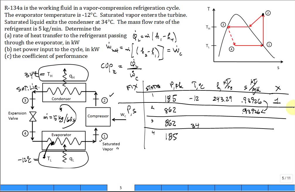
Calc Vapor Compression Refrigeration Cycle R134a Youtube

Analysis Of A Vapor Compression Refrigeration Cycle Application
Thermodynamic Calculations Of Vapor Compression Refrigeration
Vapor compression cycle working diagram a refrigeration system can also be used as a heat pump in which the useful output is the high temperature heat rejected at the condenser.
Vapor compression cycle design. Maximum power of compressor is 600 w. Alternatively a refrigeration system can be used for providing cooling in summer and heating in winter. The most widely used refrigeration cycle is the vapor compression refrigeration cycle. In this paper the case study was extended to include an expanded search space inclusion of utility streams and practical design criteria.
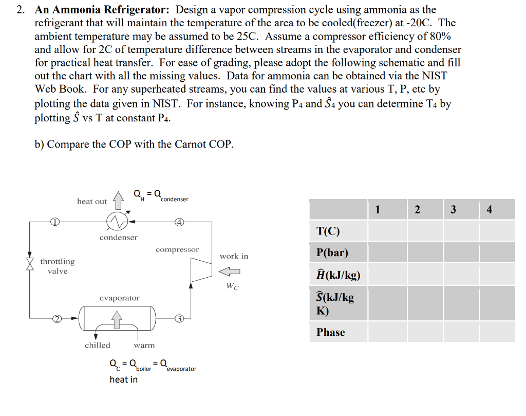
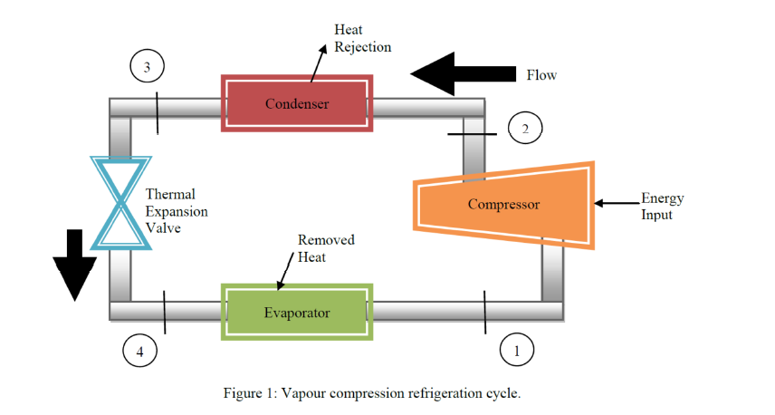
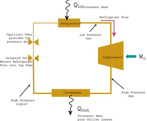
Evaporator compressor condenser and expansion or throttle valve. All such systems have four components. A compressor a condenser a thermal expansion valve also called a throttle valve or metering device and an. Your client coolarama pty ltd is a manufacturer of vapor compression cycle refrigeration units for use in commercial air conditioners.
Figure 1 depicts a typical single stage vapor compression system. The vapor compression refrigeration cycle has four components. Vapor compression uses a circulating liquid refrigerant as the medium which absorbs and removes heat from the space to be cooled and subsequently rejects that heat elsewhere. A refrigerant design problem for a vapor compression refrigeration cycle was presented previously gani et al 2017.
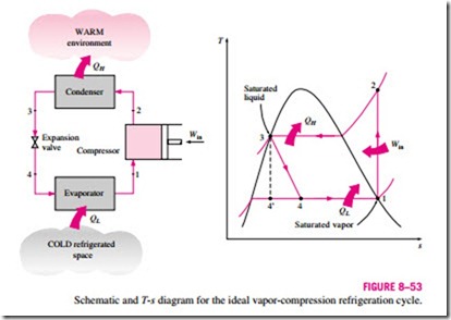
We want to design a vapor compression refrigeration cycle to absorb heat from a cool environment and reject it to a warm environment. In vapor compression cycle you mentioned you are facing a challenge. Considering a usual cop of 3 for the cycle 1800 w of. Lets start with some calculations.
In an ideal vapor compression refrigeration cycle the refrigerant enters the compressor as a saturated vapor and is cooled to. Coolarama s first generation refrigeration unit comprised a single cycle through a compressor condenser throttling valve and evaporator. A cooler where we reject the heat a throttle a heater where we absorb the heat and a compressor.
Power And Refriger A Tion Cycles The Ideal Vapor Compression

Design A Refrigeration System The Engineering Mindset
Design Of Vapor Compression Refrigeration Cycles

Vapor Compression Refrigeration Systems Refrigerator

Schematic Of A Multiple Evaporator Vapor Compression Cycle For
Solved A Refrigeration System Is To Be Designed To Mainta

Actual Vapor Compression Cycle Youtube
Vapor Compression Cooling For High Performance Applications
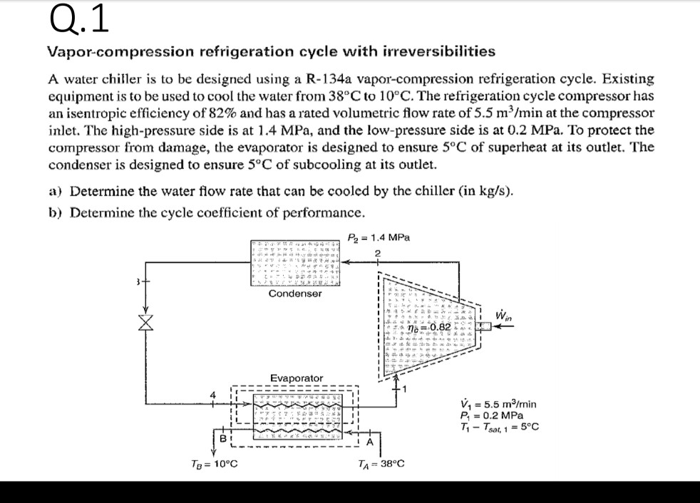
Solved Q 1 Vapor Compression Refrigeration Cycle With Irr

Temperature Entropy Diagram Of The Vapor Compression Cycle

Vapor Compression Refrigeration An Overview Sciencedirect Topics
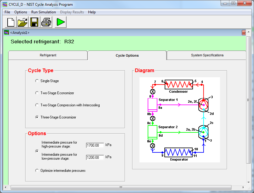
Nist Standard Reference Database 49 Nist

Thermodynamic Calculations Of Two Stage Vapor Compression